Copper Low Fin Tube Machine/Out fin and inner grooved tube machine

Short Description:

Out fin tube machine (copper low fin tube)

Copper Low Fin Tube Machine/Out fin and inner grooved tube machine


Product Detail

Product Tags

Copper Low Fin Tube Technical proposal

1.Out fin and inner grooved tube machine

Straight out fin and inner grooved tube machine is used to produce the out fin and inner grooved tube, it is with the character of low investment and easy operation.

1.1. Technical parameter

1.1. Main motor: Main motor: 7.5kW 1440rpm.
1.2. Producing speed: 0.80~1.20meter/min (the speed is different according to different tube specification)
1.3. Tube to be produced: 12.7mm~25.4mm
1.4. Fin numbers (each inch): 19~60fins (for stainless steel tube max fin number is 40fins)
1.5. Fin height: 0.7mm~1.6mm (copper tube)
1.6. Inner groove number: 8~70teeth(70teeth only for copper tube)
1.7. Tube length: 300mm~6000mm
1.8. Tube material: Copper, aluminum, copper nickel, brass, carbon steel and stainless steel tubes
1.9. Compressed air pressure: 0.4-0.8Mpa 0.2m3/h
1.10. Machine overall dimension: 13500mm x 1350mm x 1150m Length x Width x Height
1.11. Electricity power: 380V 50HZ 3phases

1.2 Machine configuration and characteristic

The out-fin tube machine is composed of following structure: tube storage table, fin tube main machine, tube input and output frame system, mandrel table, hydraulic station, electrical control cabinet and accessories.
1.2.1. The tube storage table is used to load the raw material tube which is going to be produced, and its material is stainless steel with polished surface in case of tube surface of scratch. The tube storage table dimension is 6000x500mm.
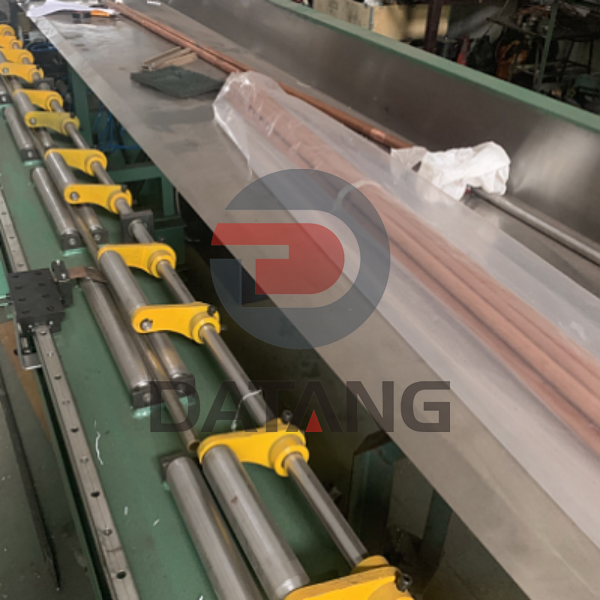
low fin tube machine

1.2.2. The main part of the equipment is the fin tubes main machine which is composed of rolling head, base, hydraulic cylinder and cooling water tank.
The fin tube rolling head is welded by steel plate and the plate is quenched to release the tension, and make sure the machine head verticality to be ≤0.05mm to make sure the three shaft pin holes concentricity to be≤0.01mm. The machine head is painted with anti-dust paint.
The hydraulic cylinder feeds the power to blades stably to ensure the machine stable running.
The angle plate is one time fabricated, and the plate is cut by individual cutting.
The knife blade is exposed design, it is easy to be observed during production and cooling, as well as blades changing. The main motor driving is done by tri-angle belt.
Machine head overall dimension: 1300x1300x1600mm
Material: A3 thickness10mm

finned tube machine

1.2.3. Smooth tube section jumping system.
The smooth tube section jumping system is the device for smooth tube remaining, it is composed of jumping frame, pneumatic cylinder, tube clamping block, the tube clamping block is driven by pneumatic cylinder, when the smooth section No. is set in touch screen, and sensor senses tube, the cutting blades will open automatically, pneumatic cylinder will clamp the tube and pull out to form the smooth section.

inner grooved fin tube machine

1.2.4. The tube input and output system, it is composed of jumping signal sending device, tube storage frame device, guiding shaft, pinch roller device, synchronization hoisting device and tube pushing shaft. The tube output frame body adopts whole piece channel steel to increase the strength, the straight line guiding convey is connected with sensor which enable the jumping to be accurate and stable, the synchronization hoisting device adjusts the frame body position up and down to roll the different size copper tubes. The tube pushing shaft drives the tube into machine head, and it returns automatically when producing is finished.
Output tube frame: 250x7000 H section
There are groups φ41x350mm chrome plated rollers.
The tube smooth section jumping sensors are place with tube input and output frame.
The tube input and output system dimension: 6000x850x1200mm

1.2.5. Mandrel frame, the mandrel frame is composed of frame body, mandrel, and copper tube holding pipe. The tube input will be inserted into the holding pipe, when tube reaches its position, the mandrel will enter into copper tube, teeth/smooth plug is placed at the top side of the mandrel. The mandrel adjusting device in front and in the back can easily adjust the position of inner grooved teeth plug to make sure the inner grooved copper tube quality. The mandrel adjusting device and locking device are placed at the end.
Mandrel frame dimension: 6000x300x1200mm
1.2.6 Electrical control system
The electrical control system adopts international brand, PLC control and inverter, other electrical components adopt top Chinese brand, blades feeding in is PLC controlled.
1.2.7. Pneumatic system
The pneumatic system adopts Chinese brand components. The pneumatic system enables all pneumatic work properly.
1.2.8. The hydraulic system provides the hydraulic power to the blades feeding distance to control the fin height.
Hydraulic station tank 800x530x450: 1pcs
Hydraulic station motor 100L1-4 2.2kW: 1pcs
Elec-magnetic valve DSG-02-3C6-DL-D24: 1pcs
Air cooler AH0608T-CA AC-380V 50HZ: 1pcs
Gear pump CBN-E310 10ml/r: 1pcs
Hydraulic pressure: 16Mpa
1.2.9 Machine paint
The main machine paint to be confirmed after contract is signed. Electrical control panel paint color is standard milk white, and anti-dust treatment to be done before paint.

1.3. Supply scope

1.3.1. Seller supply scope
1.3.1.1. Main machine

No. Description Unit Quantity Remark

1

Fin tube machine main machine

set

1

2

Electrical control cabinet

set

1

3

Pressing roller cylinders and pneumatic system

set

1

4

Hydraulic system

set

1

1.3.1.2. Enclosed spares(1size copper tube)

No. Description Unit Quantity Remark

1

Blade (size to be confirmed by buyer)

set

1

Blade (size to be confirmed by buyer)

2

Washer (size to be confirmed by buyer)

set

1

Washer (size to be confirmed by buyer)

3

Teeth Plug (size to be confirmed by buyer)

pcs

1

Teeth Plug (size to be confirmed by buyer)

4

Knurling blade(size to be confirmed by buyer)

pcs

1

Knurling blade(size to be confirmed by buyer)

5

Angle board(size to be confirmed by buyer)

set

1

Angle board(size to be confirmed by buyer)

6

Guiding shaft

pcs

1

1.3.1.3. Technical documents including:

Machine maintenance instruction 1set
Electrical theory drawing: 1set
Consumable parts drawing: 1set
Hydraulic theory drawing: 1set

1.4. Buyer supply scope

1.4.1. Electrical power supplying including cable and the cabinet.
1.4.2. Compressed air
1.4.3. Measurement tools
1.4.4. Equipment foundation, include all anchor bolts and pre-bedded steel plates which is necessary
1.4.5. Tube for testing


  • Previous:
  • Next:

  • Write your message here and send it to us